From Datasheet to Review Package: A Runnable PCB Harness
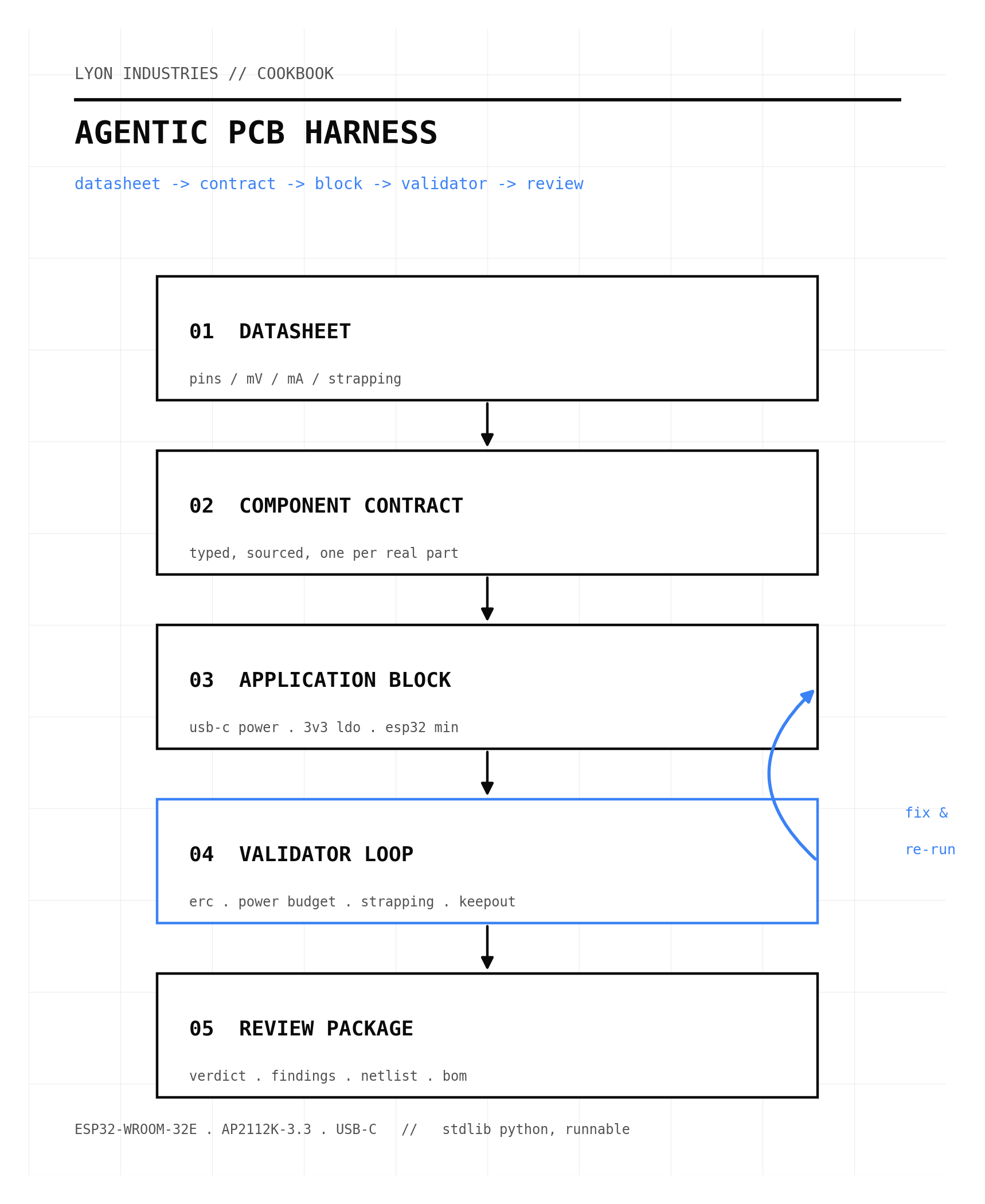
Build a standard-library Python harness that turns datasheet facts into sourced component contracts, composes them into reusable application blocks, and runs deterministic validators - ERC, power budget, ESP32 strapping, antenna keepout - to emit a review package for a USB-C powered ESP32-WROOM-32E board before any copper is routed.
- Published
- Jun 1, 2026
- Reading
- 8 min
- Author
- Christopher Lyon
- Filed
- Cookbook
You can ask a language model for a schematic and get something that looks convincing.
The convincing part is the problem. A board can show the right microcontroller symbol and still miss the boot pins. It can include a regulator and still have no current margin. It can place a PCB-antenna module and still flood copper through the keepout. None of that shows up in a casual read of the schematic. It shows up on the bench, after the boards arrive.
The white paper Agentic Electrical Engineering For PCB Design argues that AI becomes useful in electronics when it works through five linked objects: requirements, component contracts, application blocks, validators, and a review package. This cookbook builds that pipeline for one real circuit - a USB-C powered, UART-programmable ESP32-WROOM-32E board - in about 400 lines of standard-library Python, and shows the validators catching the failures that "looks right" hides.
The short version:
A component contract is a sourced, typed record of a real part. An application block wires contracts into a known pattern. A validator is a deterministic check that runs before a human looks at the design. The review package is what the human inspects. Nothing here routes copper, and that is the point: the harness stops at a checked netlist plus a written review, which is exactly the layer where an agent can be useful and exactly the layer where mistakes are cheap to fix.
What You Will Build
A small library, harness.py, that holds the domain model, the validators, and the emitters. A sourced part library, contracts.py, that encodes two real datasheets. A build script that produces a review package, a KiCad-style netlist, and a bill of materials. And a test suite that proves each validator bites on a real injected fault.
The worked board:
Two parts carry the design, and every electrical fact below traces to their datasheets:
- ESP32-WROOM-32E - Espressif's Wi-Fi/BLE module. Power on pin 2 (3V3), grounds on pins 1, 15, and 38, enable on pin 3.1Espressif Systems. ESP32-WROOM-32E & ESP32-WROOM-32UE Datasheet, v2.0. Pin definitions (Table 3), strapping defaults (Table 4), boot modes (Table 6), recommended operating conditions (Table 14: VDD33 3.0/3.3/3.6 V, external supply current min 0.5 A), current consumption (Table 16: TX peak 379 mA)... Recommended supply is 3.0 to 3.6 V, and the datasheet asks for an external supply able to deliver at least 0.5 A, against TX current peaks near 379 mA.1Espressif Systems. ESP32-WROOM-32E & ESP32-WROOM-32UE Datasheet, v2.0. Pin definitions (Table 3), strapping defaults (Table 4), boot modes (Table 6), recommended operating conditions (Table 14: VDD33 3.0/3.3/3.6 V, external supply current min 0.5 A), current consumption (Table 16: TX peak 379 mA)...
- AP2112K-3.3 - a 600 mA fixed 3.3 V LDO in SOT-23-5, dropout 250 mV at full load, input 2.5 to 6.0 V, stable with 1 µF ceramics in and out.2Diodes Incorporated / BCD Semiconductor. AP2112 - 600mA CMOS LDO Regulator with Enable, Rev 2.0. 3.3 V ±1.5 %, 600 mA, dropout 250 mV at 600 mA, VIN 2.5 to 6.0 V, stable with 1.0 µF ceramic input and output, SOT-23-5 pinout (Fig 2). https://www.diodes.com/assets/Datasheets/AP2112.pdf
Five volts from USB into a 250 mV-dropout regulator is comfortable. Six hundred milliamps of supply against a half-amp draw is a real but tight 17 percent margin - the kind of number you want a tool to state out loud rather than leave you to notice.
The Mental Model
Think of the harness as a translation layer that refuses to lose provenance:
| Input | Step | Output |
|---|---|---|
| Datasheet facts | Component contract | typed pins, roles, electrical envelope, citation |
| Contracts | Application block | a wired sub-circuit with named nets |
| Block | Validator loop | findings: errors, warnings, info |
| Findings | Review package | a verdict and a checklist a human can sign off |
The validators reason about pin roles - power in, power out, ground, digital in, strapping - not pin names. That is what lets one strapping check cover every ESP32 design instead of one board.
The Component Contract
The model is four small dataclasses. A pin has a role and, for power pins, an operating envelope. A component is a sourced set of pins. Roles are an enum because the validators switch on them.
class Role(str, Enum):
    POWER_IN = "power_in"      # consumes a rail (ESP32 3V3, LDO VIN)
    POWER_OUT = "power_out"    # sources a rail (LDO VOUT, USB VBUS)
    GROUND = "ground"
    DIGITAL_IN = "digital_in"  # e.g. EN
    DIGITAL_IO = "digital_io"  # GPIO / strapping pins
    PASSIVE = "passive"        # resistor / capacitor terminal
    NC = "nc"

@dataclass(frozen=True)
class Pin:
    number: str
    name: str
    role: Role
    v_min: float | None = None
    v_typ: float | None = None
    v_max: float | None = None
    strap_default: str | None = None     # "pull-up" | "pull-down"
    strap_rule: str | None = None        # human-readable constraint
    note: str | None = None
Here is the ESP32 contract. Every field is a datasheet fact, and the source is the citation that makes the contract auditable. Note that GPIO6 to GPIO11 do not appear: on the WROOM module they are bonded to the internal SPI flash and never led out, so a designer cannot misuse them.1Espressif Systems. ESP32-WROOM-32E & ESP32-WROOM-32UE Datasheet, v2.0. Pin definitions (Table 3), strapping defaults (Table 4), boot modes (Table 6), recommended operating conditions (Table 14: VDD33 3.0/3.3/3.6 V, external supply current min 0.5 A), current consumption (Table 16: TX peak 379 mA)... The contract encodes the constraint that matters most - MTDI must stay low at boot, because high selects 1.8 V flash and bricks a 3.3 V module.
ESP32_WROOM_32E = Component(
    part="ESP32-WROOM-32E",
    description="Wi-Fi/BLE module, ESP32-D0WD-V3, 4 MB flash, PCB antenna",
    package="Espressif WROOM (SMD, 38-pad)",
    source="Espressif ESP32-WROOM-32E Datasheet v2.0, Table 3/4/6/14/16",
    draws_current_a=0.5,  # Table 14, minimum external supply current
    pins=(
        Pin("1", "GND1", Role.GROUND),
        Pin("2", "3V3", Role.POWER_IN, v_min=3.0, v_typ=3.3, v_max=3.6),
        Pin("3", "EN", Role.DIGITAL_IN,
            strap_rule="High=run; do not leave floating (Table 3)"),
        Pin("14", "MTDI", Role.DIGITAL_IO, strap_default="pull-down",
            strap_rule="Low at boot selects 3.3 V flash; High selects 1.8 V (Table 4)"),
        Pin("15", "GND15", Role.GROUND),
        Pin("24", "GPIO2", Role.DIGITAL_IO, strap_default="pull-down"),
        Pin("25", "GPIO0", Role.DIGITAL_IO, strap_default="pull-up",
            strap_rule="High=SPI boot, Low=download (Table 6)"),
        Pin("34", "RXD0", Role.DIGITAL_IO),
        Pin("35", "TXD0", Role.DIGITAL_IO),
        Pin("38", "GND38", Role.GROUND),
    ),
)
Application Blocks
A block places parts on a shared board and wires nets. This is the reusable layer: "USB-C power in", "3.3 V LDO", "ESP32 minimal". The LDO block is the clearest example - it ties enable high so the regulator is always on, and it places the two 1 µF ceramics the datasheet requires for stability.2Diodes Incorporated / BCD Semiconductor. AP2112 - 600mA CMOS LDO Regulator with Enable, Rev 2.0. 3.3 V ±1.5 %, 600 mA, dropout 250 mV at 600 mA, VIN 2.5 to 6.0 V, stable with 1.0 µF ceramic input and output, SOT-23-5 pinout (Fig 2). https://www.diodes.com/assets/Datasheets/AP2112.pdf
def block_ldo_3v3(b: Board, ref: str = "U2") -> None:
    b.add(ref, AP2112K_33)
    b.wire("+5V", ref, "VIN")
    b.wire("3V3", ref, "VOUT")
    b.wire("GND", ref, "GND")
    b.wire("+5V", ref, "EN")          # EN high = enabled; tie to VIN for always-on
    b.add("C_IN", capacitor("1uF"))
    b.wire("+5V", "C_IN", "1")
    b.wire("GND", "C_IN", "2")
    b.add("C_OUT", capacitor("1uF"))
    b.wire("3V3", "C_OUT", "1")
    b.wire("GND", "C_OUT", "2")
The ESP32 block adds the parts a module needs to boot and be programmed: a 10 kΩ pull-up and 1 µF on EN for a clean power-up reset, a 10 kΩ pull-up on GPIO0 for normal SPI boot, 10 µF bulk and 0.1 µF local decoupling on the rail, and a six-pin UART header for an external programmer.
The Validator Loop
Each validator takes the board and yields findings. They are independent and deterministic: same board in, same findings out, no network, no model call. The strapping validator is where the datasheet turns into a rule that bites:
def v_strapping(board: Board):
    for inst in board.instances:
        for p in inst.component.pins:
            if p.strap_rule is None:
                continue
            net = board.net_of(inst.ref, p.name)
            net_name = net.name if net else None
            if p.name == "EN":
                if net is None or not board.has_pullup_to(net_name, "3V3"):
                    yield Finding(Severity.ERROR, "STRAP.EN",
                                  f"{inst.ref}.EN must not float: needs a pull-up to 3V3")
            elif p.name == "MTDI":
                if board.shares_net_with_rail(inst.ref, p.name, "3V3") or \
                        (net_name and board.has_pullup_to(net_name, "3V3")):
                    yield Finding(Severity.ERROR, "STRAP.MTDI",
                                  f"{inst.ref}.MTDI is pulled high: selects 1.8 V flash "
                                  f"and bricks a 3.3 V module")
The power-budget validator sums the current drawn by every power_in pin on a rail and compares it to what the rail's power_out source can supply. If the draw wins, that is a blocking error; if there is margin, it reports the headroom so a tight design announces itself:
def v_power_budget(board: Board):
    for net in board.nets:
        sources = [board._instances[n.ref] for n in net.nodes if n.pin.role == Role.POWER_OUT]
        if not sources:
            continue
        supply = sum(s.component.sources_current_a or 0.0 for s in sources)
        draw = sum((board._instances[n.ref].component.draws_current_a or 0.0)
                   for n in net.nodes if n.pin.role == Role.POWER_IN)
        if draw > supply:
            yield Finding(Severity.ERROR, "PWR.BUDGET",
                          f"rail {net.name}: draw {draw:.3f} A exceeds supply {supply:.3f} A")
        elif supply > 0 and draw > 0:
            margin = (supply - draw) / supply * 100
            yield Finding(Severity.INFO, "PWR.MARGIN",
                          f"rail {net.name}: {draw:.3f} A of {supply:.3f} A ({margin:.0f}% headroom)")
The remaining validators check required fields and source citations, run a basic ERC (no single-pin floating nets, no power rail without a source, no two sources fighting on one net), check that every power pin's rail sits inside the part's voltage envelope, confirm the rail decoupling and the LDO's input and output capacitors are present, and require a declared keepout zone when a PCB-antenna module is used.1Espressif Systems. ESP32-WROOM-32E & ESP32-WROOM-32UE Datasheet, v2.0. Pin definitions (Table 3), strapping defaults (Table 4), boot modes (Table 6), recommended operating conditions (Table 14: VDD33 3.0/3.3/3.6 V, external supply current min 0.5 A), current consumption (Table 16: TX peak 379 mA)...
Running It
python3 build.py builds the board, runs the seven validators, writes the artifacts, and exits non-zero if anything blocks - so this can gate a CI job. On the finished board it reports two info lines and nothing else:
INFO  PWR.MARGIN   rail +5V: 0.600 A of 1.500 A (60% headroom)
INFO  PWR.MARGIN   rail 3V3: 0.500 A of 0.600 A (17% headroom)

13 components, 9 nets, 2 findings
RESULT: READY FOR HUMAN REVIEW
The 3V3 rail's 17 percent headroom is exactly the kind of fact you want surfaced. It is fine for this design, but it is the first number to revisit if the firmware ever drives the radio harder. The emitted review package records it alongside the open assumptions:
# Review Package - esp32-usb-c-min

**Verdict:** READY FOR HUMAN REVIEW
**Components:** 13   **Nets:** 9
**Findings:** 0 error, 0 warning, 2 info

## Open assumptions
- USB-C source advertised current taken as 1.5 A; confirm against the actual
  charger / PD contract before relying on the 5 V budget.
- EN RC values (10k + 1uF) follow the Espressif reference design.
- Layout, antenna keepout geometry, and thermal relief are out of scope.
The build also writes a flat KiCad-style netlist you can import and run your own ERC against, and a bill of materials with a source column, so every line on the board points back to a datasheet:
ref,part,value,package,source
C_BULK,C-10uF,10uF,0402,generic X7R 0402 >=10 V
...
U1,ESP32-WROOM-32E,,"Espressif WROOM (SMD, 38-pad)","Espressif ... Datasheet v2.0"
U2,AP2112K-3.3,,SOT-23-5,"Diodes/BCD AP2112 Datasheet Rev 2.0"
When It Bites
A review package that only ever says "ready" is theatre. The harness earns its keep on broken input. python3 demo_broken.py injects four faults that each pass a casual eyeball and fail on the bench - a USB source advertising too little current, a PCB-antenna module with no keepout, EN tied straight to the rail with no defined pull-up, and MTDI pulled high. The harness blocks on all four:
ERROR ERC.FLOAT    net 'EN' has fewer than two connections: U1.EN
ERROR PWR.BUDGET   rail +5V: draw 0.600 A exceeds supply 0.300 A
ERROR RF.KEEPOUT   U1 is a PCB-antenna module but no keepout zone is declared
ERROR STRAP.EN     U1.EN must not float: needs a pull-up to 3V3
ERROR STRAP.MTDI   U1.MTDI is pulled high: selects 1.8 V flash and bricks a 3.3 V module
WARN  DEC.BULK     3V3 rail has no >=10uF bulk capacitor
WARN  STRAP.BOOT   U1.GPIO0 has no pull-up to 3V3; default boot relies on the module's internal pull-up
The MTDI line is the one that matters. A schematic with MTDI pulled to 3V3 looks tidy - a strapping pin with a defined level. It also selects 1.8 V for the flash supply on a module built for 3.3 V, and the board will not boot. That failure is invisible in a symbol-by-symbol read and obvious to a rule that knows what the pin means.
python3 test_harness.py runs the good board and six broken variants as assertions, so each validator has a test proving it fires on the fault it is meant to catch.
What This Is Not
This is a schematic-level harness, and it is honest about its edges.
It does not route copper. Placement, the keepout geometry, trace widths, and thermal relief are the EDA tool's job and the human's job; the harness only insists a keepout is declared. It checks nets, not locality - removing the LDO's output capacitor does not fire an error here, because the output net is the 3V3 rail and the ESP32 decoupling still sits on it. A net-level model cannot see that the cap moved away from the regulator, and pretending otherwise would be the same "looks right" failure one layer up. The USB current assumption is exactly that - an assumption, flagged in the review package, to be replaced by the real power-delivery contract.
None of this is a limitation to apologize for. It is the scope the white paper named: produce a reviewable first pass, with the reasoning inspectable, before anyone treats the output as a board.
The Next Build
Three extensions follow directly. Parse the contracts out of the datasheet PDFs instead of hand-encoding them, with the source page cited per field, so the contract library grows without a human transcribing pin tables. Emit a netlist a headless KiCad can import and ERC automatically, closing the loop between this harness and a real EDA check. And widen the block library - USB-C with power delivery negotiation, a buck instead of an LDO for higher-current loads, a second MCU family - so the same validators cover more of the designs an agent will actually be asked to draft.
The harness is the part that has to exist first. An agent that can draft a board is interesting. An agent whose board arrives with a sourced contract for every part, a passing power budget, and a strapping check that knows MTDI from EN is one an engineer can actually review.
Reproduce This
Everything runs on a stock Python 3.10 or newer, no packages:
python3 build.py          # -> outputs/, exit 0 = READY FOR HUMAN REVIEW
python3 demo_broken.py    # -> the four-fault review package
python3 test_harness.py   # good board passes, broken boards fail by code
The full harness.py, contracts.py, and tests live in the project workspace. The two parts are real, the facts are cited, and the validators are the cheap insurance you buy before the boards ship.
Footnotes
-
Espressif Systems. ESP32-WROOM-32E & ESP32-WROOM-32UE Datasheet, v2.0. Pin definitions (Table 3), strapping defaults (Table 4), boot modes (Table 6), recommended operating conditions (Table 14: VDD33 3.0/3.3/3.6 V, external supply current min 0.5 A), current consumption (Table 16: TX peak 379 mA), antenna keepout (Section 3.1, Note A). https://documentation.espressif.com/esp32-wroom-32e_esp32-wroom-32ue_datasheet_en.pdf ↩ ↩2 ↩3 ↩4
-
Diodes Incorporated / BCD Semiconductor. AP2112 - 600mA CMOS LDO Regulator with Enable, Rev 2.0. 3.3 V ±1.5 %, 600 mA, dropout 250 mV at 600 mA, VIN 2.5 to 6.0 V, stable with 1.0 µF ceramic input and output, SOT-23-5 pinout (Fig 2). https://www.diodes.com/assets/Datasheets/AP2112.pdf ↩ ↩2